SGTools: Difference between revisions
| Line 60: | Line 60: | ||
=== Editor Setting (Menu - Tools - Option) === | === Editor Setting (Menu - Tools - Option) === | ||
[[File:SGT Editor Setting.png| | [[File:SGT Editor Setting.png|480x480px]] | ||
'''In Editor Setting''' | '''In Editor Setting''' | ||
| Line 79: | Line 79: | ||
* "Start Page" to show at power on | * "Start Page" to show at power on | ||
* power on "Backlight Brightness" level | * power on "Backlight Brightness" level | ||
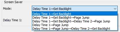
* select one of the "Screen Saver Mode", user can select one of the following with related parameter | * select one of the "Screen Saver Mode", user can select one of the following with related parameter [[File:Screen saver mode.png]] | ||
* set "Buzzer" beeping length (0=no sound) | * set "Buzzer" beeping length (0=no sound) | ||
* set RTC (real time clock) operation mode | * set RTC (real time clock) operation mode [[File:RTC mode.png|407x407px]] | ||
{| class="wikitable" | {| class="wikitable" | ||
| Line 117: | Line 117: | ||
* Partition2 can be create for data storage | * Partition2 can be create for data storage | ||
* LAN settings only available for SmartLCD equipped with Ethernet interface[[File:SGT LAN Setting a.png|480x480px]] | * LAN settings only available for SmartLCD equipped with Ethernet interface [[File:SGT LAN Setting a.png|480x480px]] | ||
* IP is the static assigned IP address for a SmartLCD | * IP is the static assigned IP address for a SmartLCD | ||
* IP, TCP Port, Mask and GW(Gateway) are standard Ethernet config parameters | * IP, TCP Port, Mask and GW(Gateway) are standard Ethernet config parameters | ||
Revision as of 14:32, 10 May 2025
TOPWAY SGTools
SGTools is an UI design tools for Smart LCD. SGTools allowing designs UI with zero coding. It dramatically simplifies and speeds up the whole product design process
SGTools Layout

| A. | menu and config | file tools for project open, save, project options |
| B. | alignment tools | alignment and display filter tools; with compile and download tools |
| C. | elements for UI | display elements tools |
| D. | resource (VP, icons, etc) | Resource windows (right click on the resources); built new page; import pictures (IMG_BKG, IMG_ICO, IMG_ANI); allocated VP variable (VP_N16, VP_N32, VP_N64); user file, etc... (*1) |
| E. | UI editing area | The working area for composing the display page. User could build element onto the page. |
| F. | Elements or page properties | Display the selected element properties or Page properties |
| G. | prompt output area | Prompt output window show the compiling information, warning and error information |
SGTools Menu - File
Start (Menu - File - Welcome)
At the start up of the SGTools, It will pop up a Welcome interface for use to select the previous Edited Project, Create a New Project or Open Project somewhere else.

New Project (Menu - File - New Project)
.png) For New Project, user can type in the project name and select the folder for that project. It is important to ensure to select the correct screen size that match the target Smart LCD. (0°/180° for landscape projects), (90°/270° for portrait projects). After click the OK button, SGTools will create a folder in to the Project Folder.
For New Project, user can type in the project name and select the folder for that project. It is important to ensure to select the correct screen size that match the target Smart LCD. (0°/180° for landscape projects), (90°/270° for portrait projects). After click the OK button, SGTools will create a folder in to the Project Folder.

Open Project (Menu - File - Open Project)
.png) Open Project look for the project folder with .tpj or .tp9 file inside
Open Project look for the project folder with .tpj or .tp9 file inside
Save (Menu - File - Save)
.png) Save the current project.
Save the current project.
Save As (Menu - File - Save As)
Save the current project another (folder) name.
Close Project (Menu - File - Close)
.png) Close the current project.
Close the current project.
SGTools Menu - Tools
Editor Setting (Menu - Tools - Option)

In Editor Setting
- Fine adjust all the image color tone during compile by setting Image Gamma
- Select Compile Options
- Output Project Image File (see “Download the display project” section for details)
- Open Output folder after compile
- Compile Project before download
- Save the project before compile
- Compile Orphan Background Images
Project Setting (Menu - Tools - Project Setting)
.png) Project Setting
Project Setting

- "Start Page" to show at power on
- power on "Backlight Brightness" level
- select one of the "Screen Saver Mode", user can select one of the following with related parameter
- set "Buzzer" beeping length (0=no sound)
- set RTC (real time clock) operation mode
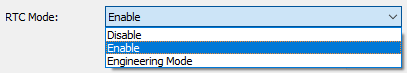


| RTC Mode | Operating with RTC battery | Operating without RTC battery | Descriptions |
|---|---|---|---|
| Enable | 1st power up takes 6s;
next power up takes 1s |
every power up takes 6s | RTC run with correct init |
| Disable | every power up takes 1s | every power up takes 1s | RTC stop |
| Engineering Mode | every power up takes 1s | every power up takes 1s | RTC run without init, it might not run correctly. It is NOT suggested for production setting |
- set power on "RS232 Baudrate"
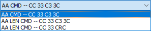
- set “Command Format”, three kinds of command Format are available.
- set “Command Timeout” (0=no timeout)
- set power on "Country Code" for ASCII display
- set power on "Code Page" for ext. char & decoding
- set “Enable ACK” to provide command responses; “:>” : ready for new command; “!>” : command error
- set "Touch-Key lock on touch" to lock the touch down key and action on release
- set "Upside-down" to show the generate 180 deg rotated display content
- Partition2 can be create for data storage

- LAN settings only available for SmartLCD equipped with Ethernet interface
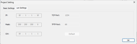
- IP is the static assigned IP address for a SmartLCD
- IP, TCP Port, Mask and GW(Gateway) are standard Ethernet config parameters
- TFTP Port is for remote TFTP file access

Font Setting (Menu - Tools - Font Setting)
.png) There are 3 sections of Fonts.
There are 3 sections of Fonts.
Font Config <1>, the Font Width and Height are fixed and mainly for ASCII Char. (with some default font, vary by model)


Font Config <2>, provide more free option about Size and Decoding selection. (without font by default)


Font Config <3>, support True Type Font (TTF) form some of the model. (without font by default)

Right click on the font table, select "build" could build the font with several options. It is suggested to delete the un-used Font area for reduce the memory allocation.
Compile (Menu - Tools - Compile)
.png) Compile [F7]
Compile [F7]
After finish the layout, "Built Project Files" will compile all the resource and font etc in to a set of files. It could download or copy to the Smart LCD at any time. It will pop-up the output folder inside the Project Folder
Download to Module (Menu - Tools - Download to Module)
.png) Download to Module [F9]
Download to Module [F9]
After connect the Smart LCD USB to user PC, the Smart LCD will appear as a removable drive. Using "Download to Module" could copy the compiled project file into the Smart LCD.

Note. it will refuse to download without Smart LCD
